

Chiller Plant Design: Complete Guide to 7 Essential Steps
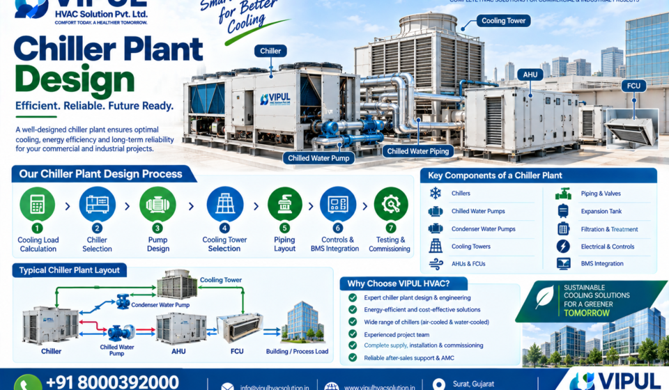
Chiller plant design is the engineering process of designing a complete centralized cooling system that produces chilled water and distributes it to AHUs, FCUs, process equipment or other cooling loads.
A properly designed chiller plant is not simply a matter of selecting a chiller with a particular TR capacity. The design must consider cooling load, load profile, chilled-water temperatures, flow rate, chiller configuration, pumps, cooling towers, piping, controls, redundancy, plant space, energy performance and future expansion.
ASHRAE’s guidance on central chilled-water plants specifically addresses peak and annual cooling-load profiles, chillers, pumps, cooling towers, piping arrangements, controls, life-cycle optimization and commissioning.
For commercial and industrial projects, VIPUL HVAC SOLUTION PVT. LTD. provides chiller-related engineering and project services including cooling-load analysis, chiller selection, plant design, pumps, cooling towers, piping, controls, testing, commissioning, optimization and AMC.
What Is Chiller Plant Design?
Chiller plant design is the systematic planning of all major components required to generate, distribute and control chilled water.
A typical centralized chilled-water plant can include:
- Chillers
- Chilled-water pumps
- Condenser-water pumps
- Cooling towers for water-cooled systems
- Chilled-water piping
- Condenser-water piping
- AHUs
- FCUs
- Heat exchangers where required
- Expansion tanks
- Air separators
- Valves and balancing devices
- Sensors and instrumentation
- Electrical panels
- VFDs
- PLC/control systems
- BMS integration
- Insulation
- Water-treatment systems where applicable
The exact configuration depends on the building, cooling load, operating schedule, climate, process requirements and selected chiller technology.
How Does a Chiller Plant Work?
The basic cooling process can be represented as:
Chiller → Chilled-Water Pump → AHU/FCU → Building/Process Load → Return Water → Chiller
For a conventional water-cooled plant, the heat-rejection side generally follows:
Chiller → Condenser-Water Pump → Cooling Tower → Condenser → Chiller
A simplified sequence is:
Cooling Load → Chilled Water → Chiller → Heat Rejection → Cooling Tower/Air → Heat Removed
The chilled water absorbs heat from the building or process and returns to the chiller at a higher temperature. The chiller removes that heat and sends cooled water back into the distribution system.
7 Essential Steps in Chiller Plant Design
Step 1 — Calculate the Cooling Load
Cooling-load calculation is the starting point of a professional chiller plant design.
The designer should determine the actual cooling requirement rather than selecting a chiller only from building area.
Important cooling-load components include:
Building Heat Gain
- Walls
- Roof
- Windows
- Doors
- Solar radiation
- Building orientation
Internal Heat Gain
- Occupants
- Lighting
- Computers
- Electrical equipment
- Machinery
- Kitchen equipment
Ventilation Load
Fresh air can introduce sensible and latent heat into the building.
Infiltration
Uncontrolled outdoor-air infiltration can increase the cooling requirement.
Process Load
Industrial facilities may have substantial heat generated by:
- Manufacturing machinery
- Production processes
- Hydraulic equipment
- Compressors
- Furnaces
- Process tanks
- Heat exchangers
For industrial applications, process cooling requirements can be more important than conventional building cooling.
VIPUL’s industrial chiller solutions are designed around factors such as process heat load, required fluid temperature, operating schedule, flow and redundancy.
Step 2 — Determine the Chiller Plant Capacity
After calculating the cooling load, convert the requirement into appropriate chiller capacity.
Basic Conversion
1 TR ≈ 3.517 kW of cooling
Therefore:
Chiller Capacity (TR) = Cooling Load (kW) ÷ 3.517
Example
Suppose the calculated cooling requirement is:
700 kW
Then:
700 ÷ 3.517 ≈ 199 TR
So the calculated cooling requirement is approximately:
199 TR
However, this does not automatically mean that one 200 TR chiller should be purchased.
The designer must consider:
- Number of chillers
- Part-load operation
- Redundancy
- Future expansion
- Operating schedule
- Equipment availability
- Manufacturer performance data
- Maintenance requirements
ASHRAE notes that both peak load and annual cooling-load profiles can affect central chilled-water plant design.
Step 3 — Select Air-Cooled or Water-Cooled Chiller
One of the major decisions in chiller plant design is selecting the appropriate heat-rejection method.
Air-Cooled Chiller
An air-cooled chiller rejects heat directly to outdoor air.
Typical advantages
- No cooling tower
- No condenser-water pumps
- Lower water consumption
- Simpler water-side infrastructure
- Useful where cooling-tower installation is difficult
VIPUL HVAC currently provides air-cooled chiller solutions as part of its commercial and industrial chiller portfolio.
Water-Cooled Chiller
A water-cooled chiller transfers heat to condenser water, which is then cooled through a cooling tower in a conventional arrangement.
Major components
- Water-cooled chiller
- Cooling tower
- Condenser-water pumps
- Chilled-water pumps
- Chilled-water piping
- Condenser-water piping
- Controls
- Water-treatment system where required
Water-cooled plants require additional engineering for the cooling tower, condenser-water circuit and associated controls.
Step 4 — Design the Chilled-Water System
The chilled-water distribution system connects the chiller plant with AHUs, FCUs and other cooling loads.
A simplified system is:
Chiller
↓
Chilled-Water Pump
↓
Main CHW Pipe
↓
AHU / FCU / Heat Exchanger
↓
Return CHW Pipe
↓
Chiller
The design must consider:
- Chilled-water flow
- Supply temperature
- Return temperature
- ΔT
- Pipe diameter
- Pipe length
- Pressure drop
- Pump head
- Valve selection
- Control valves
- Balancing
- Insulation
- Expansion
- Drainage and air removal
Chilled-Water Flow Calculation
A commonly used relationship for water is:
Q = m × Cp × ΔT
Where:
- Q = cooling capacity
- m = mass flow rate
- Cp = specific heat of water
- ΔT = chilled-water temperature difference
For practical chilled-water calculations:
Q(kW) ≈ 4.186 × Flow (L/s) × ΔT(°C)
Example
Assume:
- Flow = 50 L/s
- Supply water = 7°C
- Return water = 12°C
- ΔT = 5°C
Then:
Q ≈ 4.186 × 50 × 5
Q ≈ 1,046.5 kW
Convert to TR:
1,046.5 ÷ 3.517 ≈ 298 TR
This is a calculation example; actual project design should use verified load, flow and equipment data.
Step 5 — Select Chilled-Water Pumps and Condenser-Water Pumps
Pumps are critical components of a central chilled-water plant.
Pump selection should consider:
- Required flow
- Total dynamic head
- Pipe pressure losses
- Equipment pressure drop
- Valve losses
- Elevation
- Operating points
- Part-load operation
- VFD requirements
- Redundancy
For water-cooled plants, condenser-water pumps must also be selected according to the condenser-water circuit and cooling-tower requirements.
Typical Pump Arrangement
Chilled-Water Pump → Chiller → Building Load → Return
For water-cooled systems:
Condenser-Water Pump → Chiller → Cooling Tower → Return
The final pump configuration depends on the plant architecture.
Step 6 — Cooling Tower Design
Cooling towers are normally required for conventional water-cooled chiller plants.
A cooling tower rejects heat from the condenser-water loop into the atmosphere.
Cooling-tower design should consider:
- Heat rejection requirement
- Entering water temperature
- Leaving water temperature
- Outdoor wet-bulb temperature
- Flow rate
- Fan power
- Approach temperature
- Water quality
- Makeup water
- Blowdown
- Noise
- Installation location
The cooling tower should not be selected independently from the chiller.
The chiller + condenser-water pumps + cooling tower + controls should be evaluated as an integrated system.
Step 7 — Controls, BMS and Plant Optimization
Modern chiller plants can use automation to coordinate:
- Chillers
- Pumps
- Cooling towers
- VFDs
- AHUs
- FCUs
- Valves
- Temperature sensors
- Pressure sensors
- Flow meters
- Energy meters
A BMS can provide centralized monitoring and control.
Important parameters can include:
- CHW supply temperature
- CHW return temperature
- Condenser-water temperature
- Differential pressure
- Flow
- Chiller status
- Pump status
- Cooling-tower status
- Energy consumption
- Alarms
- Equipment runtime
ASHRAE’s central chilled-water plant guidance includes control sequences, instrumentation, variable-speed equipment and commissioning as important elements of plant design.
Chiller Plant Layout
A basic conceptual layout can be represented as:
                 ┌─────────────────┐
                 │   COOLING LOAD  │
                 │ Building/Process│
                 └────────┬────────┘
                          │
                    Return CHW
                          │
                          ▼
                 ┌─────────────────┐
                 │     CHILLER     │
                 └────────┬────────┘
                          │
                     Supply CHW
                          │
                    ┌─────▼─────┐
                    │ CHW PUMP  │
                    └─────┬─────┘
                          │
                          ▼
                    AHU / FCU /
                   Process Load
For a water-cooled plant:
        ┌───────────────┐
        │    CHILLER    │
        └───────┬───────┘
                │
       Condenser Water
                │
          ┌─────▼─────┐
          │ CW PUMP   │
          └─────┬─────┘
                │
                ▼
        ┌───────────────┐
        │ COOLING TOWER │
        └───────┬───────┘
                │
                └──────→ CHILLER
This is a conceptual representation. Actual plant layouts require detailed hydraulic, mechanical, architectural, electrical and controls coordination.
Primary-Only vs Primary-Secondary Chilled-Water System
Chilled-water plants can use different pumping arrangements.
Primary-Only System
The same pumps circulate water through the chillers and distribution system.
Potential characteristics include:
- Simpler piping
- Fewer pumps
- Potentially lower initial complexity
- Requires appropriate flow and control strategy
Primary-Secondary System
Separate primary and secondary pumping circuits are used.
Typical arrangement:
Primary Pumps → Chillers
and
Secondary Pumps → Building Distribution
This arrangement can provide hydraulic separation between the chiller plant and building distribution system.
The appropriate architecture depends on project size, load profile, equipment requirements, control strategy and lifecycle objectives. ASHRAE discusses primary-only and primary/secondary pumping arrangements as part of central chilled-water plant design.
Chiller Plant Design Considerations
A good design should evaluate the complete system rather than focusing only on nominal chiller capacity.
1. Peak Cooling Load
The plant must handle the required design load.
2. Part-Load Performance
Buildings frequently operate below peak load.
Therefore, chiller plant performance at part load can have a significant effect on annual energy consumption.
3. Redundancy
Critical facilities may require additional capacity or standby equipment so that cooling service can continue during equipment failure or maintenance.
4. Future Expansion
If a facility is expected to expand, the plant should consider:
- Additional chiller capacity
- Pump capacity
- Pipe capacity
- Electrical infrastructure
- Plant-room space
- Cooling-tower capacity
5. Operating Hours
A 24-hour facility can have very different requirements from an office operating only during business hours.
6. Climate
Outdoor temperature affects heat rejection, especially for air-cooled equipment and cooling towers.
7. Water Availability
Water-cooled plants require consideration of water availability, treatment, makeup and blowdown.
Chiller Plant Design for Different Industries
Commercial Buildings
Applications include:
- Corporate offices
- Shopping malls
- Hotels
- Commercial complexes
- Institutional buildings
Central chilled water can distribute cooling through AHUs and FCUs.
Hospitals
Hospital HVAC design may require special consideration for:
- Operating theatres
- Patient areas
- Isolation spaces
- Ventilation
- Filtration
- Humidity control
- Critical cooling reliability
The chiller plant should therefore be coordinated with the hospital’s overall HVAC and ventilation strategy.
Pharmaceutical Plants
Pharmaceutical facilities can require tightly controlled temperature, humidity, filtration and pressure conditions.
Chiller systems may support:
- AHUs
- Cleanrooms
- Process cooling
- Temperature control
- Dehumidification systems
The exact design depends on the facility’s process and environmental requirements.
Data Centers
Data centers require highly reliable cooling.
Plant design may consider:
- 24/7 operation
- Redundancy
- Cooling capacity
- Chilled-water distribution
- CRAH/AHU systems
- Controls
- Emergency operation
- Monitoring
Industrial Plants
Industrial applications can include:
- Process cooling
- Machinery cooling
- Chemical processes
- Food processing
- Plastic manufacturing
- Textile industries
- Pharmaceutical production
Industrial chiller design should be based on the actual process heat load and required process-fluid conditions.
Chiller Plant Design vs Chiller Selection
These two terms should not be confused.
Chiller Selection
Focuses primarily on selecting the appropriate refrigeration equipment.
Chiller Plant Design
Covers the complete system:
Load → Chillers → Pumps → Piping → Cooling Tower → AHU/FCU → Controls → BMS → Commissioning
Therefore, purchasing a correctly sized chiller does not automatically mean the complete plant has been correctly designed.
Common Chiller Plant Design Mistakes
Mistake 1 — Selecting the Chiller Only by Building Area
A simple TR-per-square-foot assumption may not represent actual cooling demand.
Mistake 2 — Ignoring Part-Load Operation
The plant may spend a large portion of its operating hours below peak load.
Mistake 3 — Oversizing Equipment
Oversizing can affect initial cost, operating efficiency and control behavior.
Mistake 4 — Ignoring Pump Energy
Pump selection and control strategy influence total plant energy consumption.
Mistake 5 — Incorrect Pipe Sizing
Improper pipe sizing can create excessive pressure losses or unnecessary installation cost.
Mistake 6 — Poor ΔT Management
Low chilled-water ΔT can increase required water flow and affect plant operation.
Mistake 7 — No Redundancy Strategy
Critical facilities may need a defined approach for equipment failure and maintenance.
Mistake 8 — Treating Controls as an Afterthought
Controls should be considered during the plant-design stage.
Mistake 9 — Poor Commissioning
A correctly designed plant still needs proper testing, balancing and commissioning.
Energy Efficiency in Chiller Plant Design
Energy efficiency should be considered at the plant level, not only at the individual chiller level.
Important factors include:
- Chiller efficiency
- Part-load efficiency
- Chilled-water temperature
- Condenser-water temperature
- Pump efficiency
- VFDs
- Cooling-tower efficiency
- Pipe pressure losses
- Control sequences
- BMS optimization
- Load distribution
- Equipment staging
ASHRAE specifically emphasizes lifecycle analysis and optimization of chilled-water plants rather than considering only initial cost.
For hot and humid climates, chilled-water supply temperature and ΔT can also influence both cooling performance and pumping energy.
Chiller Plant Design Calculation Checklist
Before finalizing a project, the design team should evaluate:
Cooling Load
- Peak load
- Sensible load
- Latent load
- Ventilation load
- Process load
- Future load
Chiller
- Required TR
- Number of chillers
- Chiller type
- Compressor type
- COP/efficiency
- Part-load performance
Chilled Water
- Supply temperature
- Return temperature
- ΔT
- Flow rate
- Pipe size
- Pump head
Condenser Side
- Condenser-water flow
- Cooling-tower capacity
- Wet-bulb condition
- Condenser-water temperatures
- Pump head
Controls
- Sensors
- VFDs
- PLC
- BMS
- Alarms
- Equipment sequencing
- Energy monitoring
Project Requirements
- Plant-room space
- Maintenance access
- Noise
- Water availability
- Electrical capacity
- Future expansion
- Redundancy
VIPUL HVAC Chiller Plant Design Services
VIPUL HVAC SOLUTION PVT. LTD. provides engineered chiller solutions for commercial and industrial projects.
The company’s current chiller-related capabilities include:
- Cooling-load analysis
- Chiller plant design
- Chiller selection
- Air-cooled chillers
- Water-cooled chillers
- Pump selection
- Cooling-tower selection
- Chilled-water piping
- Condenser-water piping
- AHU integration
- FCU integration
- Electrical/control coordination
- PLC/BMS integration
- Testing
- Commissioning
- Performance optimization
- Maintenance
- AMC
VIPUL’s current chiller portfolio includes air-cooled and water-cooled systems, with listed capacities from 20 TR to 1000+ TR, depending on application and configuration.
VIPUL HVAC Chiller Plant Project Process
A typical project workflow can be:
1. Client Requirement
↓
2. Site Survey
↓
3. Cooling Load Calculation
↓
4. Chiller Capacity Calculation
↓
5. Air-Cooled / Water-Cooled Selection
↓
6. Chiller Plant Layout
↓
7. Pump & Piping Design
↓
8. Cooling-Tower Selection
↓
9. AHU/FCU Integration
↓
10. Electrical & Controls
↓
11. BMS Integration
↓
12. Equipment Supply
↓
13. Installation
↓
14. Testing & Balancing
↓
15. Commissioning
↓
16. Performance Optimization
↓
17. AMC & Maintenance
VIPUL’s published chiller project approach includes design, equipment integration, piping, controls, testing, commissioning and ongoing maintenance.
Why Choose VIPUL HVAC for Chiller Plant Design?
For a chiller plant project, the equipment is only one part of the overall solution.
VIPUL HVAC focuses on coordinating:
Cooling Load + Chiller + Pumps + Piping + Cooling Tower + AHU/FCU + Controls + Commissioning
This integrated approach is particularly relevant for large commercial and industrial projects where plant performance depends on the interaction between multiple components.
VIPUL provides chiller-related HVAC services for projects across Gujarat and nearby regions, including commercial and industrial applications.
Contact VIPUL HVAC
VIPUL HVAC SOLUTION PVT. LTD.
📞 +91 8000392000
📧 info@vipulhvacsolution.in
🌐 vipulhvacsolution.in
For a project-specific chiller plant design, the required inputs generally include building/process details, cooling-load information, operating schedule, required chilled-water temperatures, available plant space and redundancy requirements.
Frequently Asked Questions About Chiller Plant Design
1. What is chiller plant design?
Chiller plant design is the engineering process of designing the complete centralized chilled-water system, including chillers, pumps, piping, cooling towers where applicable, AHUs/FCUs, controls and commissioning.
2. How is chiller plant capacity calculated?
Capacity is normally established from the calculated cooling load. A basic conversion is:
TR = Cooling Load (kW) ÷ 3.517
The final equipment configuration also depends on load profile, redundancy, part-load performance and project requirements.
3. What are the main components of a chiller plant?
The major components can include chillers, chilled-water pumps, condenser-water pumps, cooling towers, piping, valves, AHUs, FCUs, controls, sensors and BMS.
4. Which is better: air-cooled or water-cooled chiller?
They have different infrastructure and operating characteristics. Air-cooled systems generally avoid cooling towers and condenser-water circuits, while water-cooled systems require additional heat-rejection equipment. Selection should be based on project conditions rather than a universal preference.
5. What temperature is commonly used for chilled water?
A commonly encountered design condition is 7°C supply and 12°C return, giving a 5°C ΔT, but actual design temperatures should be determined from the cooling coils, dehumidification requirements, equipment selection and project conditions.
6. Why is ΔT important in chiller plant design?
ΔT affects the amount of chilled water required for a given cooling load. A higher usable temperature difference can reduce required water flow, but the appropriate value depends on the complete system design.
7. Does a chiller plant need AHUs?
Not necessarily. Chillers produce chilled water, while AHUs or FCUs are common terminal/air-side equipment for transferring cooling to occupied spaces. Process-cooling plants may use heat exchangers or other process equipment instead.
8. Does a water-cooled chiller require a cooling tower?
A conventional water-cooled chiller plant generally uses a cooling tower for heat rejection. The exact heat-rejection arrangement depends on the selected system.
9. Why is BMS important in a chiller plant?
BMS integration can provide centralized monitoring, equipment sequencing, alarms, control and energy-performance monitoring.
10. Why is commissioning important?
Commissioning verifies that equipment, water flow, temperatures, controls and system operation perform according to the intended design.
Conclusion
Chiller plant design is a complete system-engineering process, not simply a chiller capacity selection exercise.
A successful design should connect:
Cooling Load → Chiller Selection → Pump Selection → Piping → Cooling Tower → AHU/FCU → Controls → BMS → Testing → Commissioning
The design should also account for peak load, annual load profile, part-load operation, ΔT, energy consumption, redundancy, maintenance and future expansion.
For commercial, industrial and institutional projects, VIPUL HVAC SOLUTION PVT. LTD. provides chiller-related design, supply, installation, testing, commissioning, optimization and AMC services.
For chiller plant design consultation:
+91 8000392000 | info@vipulhvacsolution.in
Recommended Linking for VIPUL HVAC
- Chiller Capacity Calculation
- Industrial Chiller Systems
- Commercial Chiller Systems
- Air Cooled Chiller
- Water Cooled Chiller
- Chiller Installation Services
- Chiller Maintenance & AMC
- AHU Systems
- FCU Systems
- BMS & HVAC Automation
- HVAC Turnkey Services


[…] Chiller Plant Design […]