
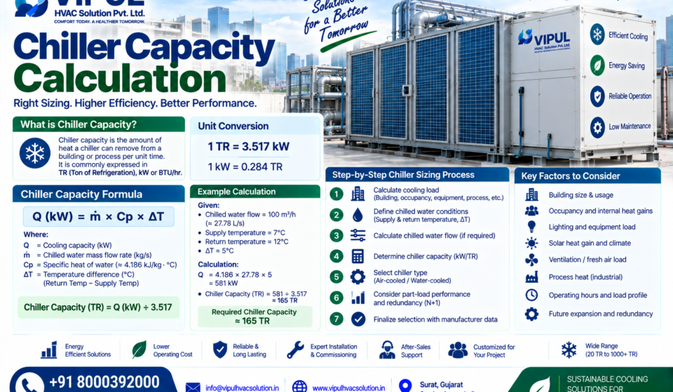

Chiller Capacity Calculation: Complete Guide to TR, kW, Flow & Cooling Load
Chiller capacity calculation is the process of determining how much cooling a chiller must provide to meet a building, process or industrial cooling load under the required operating conditions.
The basic relationship is:
Chiller Capacity (kW) = Chilled-Water Mass Flow (kg/s) × Specific Heat × Chilled-Water ΔT
And:
1 TR ≈ 3.517 kW of cooling
However, selecting a chiller is not simply a matter of dividing building area by a fixed TR value. A proper calculation should consider cooling load, chilled-water flow, supply/return temperatures, occupancy, solar gain, equipment loads, ventilation, process heat, operating schedules and future requirements. VIPUL HVAC also emphasizes cooling-load analysis before chiller selection.
What Is Chiller Capacity?
Chiller capacity is the amount of heat that a chiller can remove from a cooling system over a given period.
It is commonly expressed as:
- TR — Ton of Refrigeration
- kW — Kilowatt of cooling
- BTU/hr
A chiller’s cooling capacity is different from its electrical input power.
For example:
100 TR cooling capacity ≠ 100 kW electrical consumption.
The 100 TR represents cooling output, while electrical consumption depends on the chiller’s efficiency, operating conditions and auxiliary equipment.
A commonly used conversion is:
1 TR = 3.517 kW of cooling
Therefore:
100 TR × 3.517 = 351.7 kW cooling capacity
Why Is Chiller Capacity Calculation Important?
Correct chiller sizing is important because both undersizing and oversizing can create problems.
Undersized chiller
If the selected chiller capacity is insufficient:
- Required room temperature may not be achieved
- Process temperatures may rise
- Chiller may operate near maximum capacity
- Cooling demand may remain unsatisfied
- System reliability can be affected
Oversized chiller
An oversized system can result in:
- Higher initial investment
- Poorer operation at certain low-load conditions
- More complicated staging/control requirements
- Potentially inefficient cycling depending on equipment and controls
VIPUL’s chiller guidance specifically recommends calculating the actual cooling load instead of selecting capacity simply from building area.
Chiller Capacity Calculation: Basic Formula
There are two important approaches.
Method 1: Cooling-Load Method
If the calculated building or process cooling load is known:
Formula
Chiller Capacity (TR) = Total Cooling Load (kW) ÷ 3.517
For example, if the calculated cooling load is:
350 kW
Then:
350 ÷ 3.517 = 99.5 TR
So the calculated load is approximately:
100 TR
The final equipment selection still needs to consider operating conditions, staging, redundancy and manufacturer performance data.
Method 2: Chilled-Water Flow Method
When chilled-water flow and temperature difference are known, the cooling capacity can be calculated from the heat-transfer equation:
Q = m × Cp × ΔT
Where:
- Q = cooling capacity in kW
- m = mass flow rate in kg/s
- Cp = specific heat capacity of water, approximately 4.186 kJ/kg·K
- ΔT = chilled-water temperature difference in °C
For water:
Q(kW) ≈ m(kg/s) × 4.186 × ΔT(°C)
Then:
TR = Q(kW) ÷ 3.517
This is the fundamental heat-transfer relationship used when calculating cooling capacity from chilled-water conditions.
Chiller Capacity Calculation Example
Suppose:
Chilled-water flow = 100 m³/h
Supply water temperature:
7°C
Return water temperature:
12°C
Therefore:
ΔT = 12 − 7 = 5°C
First convert the water flow.
100 m³/h is approximately:
27.78 L/s
For water:
Q ≈ 4.186 × 27.78 × 5
Q ≈ 581 kW
Then:
TR = 581 ÷ 3.517
≈ 165 TR
Therefore, under these illustrative conditions, the chilled-water side is carrying approximately 165 TR of cooling.
This is an illustrative calculation, not a recommendation to purchase a 165-TR chiller. Actual equipment selection requires manufacturer performance data and project conditions.
Chiller Capacity Formula in SI Units
For chilled water:
Q(kW) = 4.186 × Flow(L/s) × ΔT(°C)
Then:
Capacity(TR) = Q(kW) ÷ 3.517
Therefore:
Capacity(TR) ≈ [4.186 × Flow(L/s) × ΔT] ÷ 3.517
This simplifies approximately to:
Capacity(TR) ≈ 1.19 × Flow(L/s) × ΔT(°C)
Chiller Capacity Calculation in GPM
For projects using US customary units, a commonly used approximation is:
TR = GPM × ΔT(°F) ÷ 24
Where:
- GPM = chilled-water flow in gallons per minute
- ΔT = chilled-water temperature difference in °F
For example:
500 GPM
and:
ΔT = 10°F
Then:
TR = 500 × 10 ÷ 24
TR ≈ 208.3 TR
Again, this is a hydronic-side calculation and should be checked against the actual design and equipment performance.
What Is ΔT in Chiller Capacity Calculation?
ΔT means the difference between chilled-water return temperature and chilled-water supply temperature.
For example:
7°C supply / 12°C return
Then:
ΔT = 12 − 7 = 5°C
A higher water temperature difference means more heat is transferred for the same water flow.
This is why chilled-water flow and ΔT are closely connected to chiller capacity.
Why 7°C / 12°C Is Commonly Discussed
A 7°C supply / 12°C return chilled-water arrangement provides:
ΔT = 5°C
It is a common example used for chilled-water calculations.
But actual design temperatures can differ depending on:
- Building requirements
- AHU coil design
- FCU requirements
- Process requirements
- Climate
- Chiller manufacturer
- Energy strategy
- Existing plant configuration
Therefore, don’t assume every project must use 7/12°C.
How to Calculate Chiller Capacity From Building Cooling Load
For a commercial building, the cooling load should be established first.
The calculation may include:
1. Building Envelope
- Walls
- Roof
- Windows
- Doors
- Insulation
2. Solar Heat Gain
Consider:
- Window orientation
- Glass area
- Solar exposure
- Shading
3. Occupancy
People generate sensible and latent heat.
4. Lighting
Lighting contributes to the cooling load.
5. Equipment
Examples:
- Computers
- Servers
- Machines
- Office equipment
- Kitchen equipment
6. Ventilation
Outdoor air can introduce:
- Sensible heat
- Latent heat
7. Infiltration
Uncontrolled air entering through doors and building leakage can contribute to the load.
8. Operating Schedule
A building operating:
8 hours/day
has a different load profile from a facility operating:
24 hours/day
9. Process Load
Industrial projects may have significant heat generated by machinery or production processes.
VIPUL’s current chiller project process specifically considers building area, occupancy, solar gain, lighting, equipment loads, fresh-air requirements, process loads, operating hours and climate.
Building Cooling Load Example
Suppose an HVAC engineer calculates:
| Load Component | Example Load |
|---|---|
| Building envelope | 80 kW |
| Solar gain | 70 kW |
| Occupants | 40 kW |
| Lighting | 30 kW |
| Equipment | 50 kW |
| Ventilation | 40 kW |
| Other loads | 40 kW |
| Total | 350 kW |
Then:
Chiller capacity = 350 ÷ 3.517
≈ 99.5 TR
So the calculated peak load is approximately:
100 TR
The final plant configuration could be different from a single 100-TR machine because the designer may evaluate multiple chillers, redundancy, part-load performance and future expansion.
Chiller Capacity Calculation for Industrial Applications
Industrial chiller sizing can be very different from building HVAC sizing.
For an industrial process, the calculation may start with:
Process Heat Load
For example:
Machine heat + process heat exchanger + product cooling + other heat sources
The engineer then determines:
- Required fluid temperature
- Supply temperature
- Return temperature
- Flow rate
- Fluid type
- Operating hours
- Peak process load
- Minimum load
- Redundancy
VIPUL’s industrial chiller guidance emphasizes that process cooling should be designed around the actual process rather than simply using building area.
Industrial Chiller Capacity Formula
For a liquid-cooling application:
Q = m × Cp × ΔT
However, the fluid may not always be pure water.
It could be:
- Water
- Glycol-water mixture
- Brine
- Other secondary coolant
If glycol or another fluid is used, its density and specific heat must be incorporated into the calculation rather than automatically using water properties.
Chiller Capacity Calculation for Glycol
Suppose a process uses a glycol-water mixture.
You should obtain from the fluid manufacturer:
- Specific heat
- Density
- Viscosity
- Freezing point
Then calculate:
Q = mass flow × specific heat × ΔT
Because glycol mixtures generally have different thermophysical properties from water, the result should not be calculated using the water constant without adjustment.
How Many TR Chiller Do I Need?
This is one of the most common search questions.
The answer depends on the calculated cooling load.
For example:
| Calculated Cooling Load | Approx. Cooling Capacity |
|---|---|
| 100 kW | 28.4 TR |
| 200 kW | 56.9 TR |
| 300 kW | 85.3 TR |
| 350 kW | 99.5 TR |
| 500 kW | 142.2 TR |
| 700 kW | 199.0 TR |
| 1,000 kW | 284.3 TR |
Formula:
TR = kW ÷ 3.517
These are mathematical conversions, not recommended equipment sizes.
Chiller Capacity vs Electrical Power
This distinction is extremely important.
Suppose a chiller has:
Cooling capacity = 500 TR
That does not mean:
Electrical consumption = 500 kW
Chiller efficiency is commonly expressed using metrics such as:
- COP
- kW/TR
- EER
- IPLV/NPLV or applicable part-load metrics
For example, if a hypothetical chiller has:
COP = 5
then:
Cooling output = 500 × 3.517
= 1,758.5 kW
Approximate compressor/input power based only on this simplified COP relationship:
1,758.5 ÷ 5 = 351.7 kW
Actual plant electricity consumption will also include pumps, cooling towers, fans and other auxiliaries.
Therefore:
Chiller capacity and electrical consumption are two different measurements.
Why Part-Load Performance Matters
A building rarely operates at its exact peak cooling load throughout the entire day.
For example:
Morning:
40% load
Midday:
80% load
Afternoon:
100% load
Evening:
50% load
Night:
20% load
Therefore, a chiller should not be evaluated only at full-load capacity.
ASHRAE’s chilled-water guidance emphasizes the importance of considering load profiles and operating patterns in plant sizing and operation.
Should You Add a Safety Factor to Chiller Capacity?
A common engineering question is whether to simply add 10%, 15% or 20% to the calculated load.
The answer is:
Do not blindly add a large percentage.
A professional designer should understand:
- Uncertainty in load calculation
- Future expansion
- Diversity
- Equipment availability
- Redundancy
- Part-load operation
- Manufacturer capacity ratings
- Design conditions
For example:
Calculated peak load:
500 TR
does not automatically mean:
500 × 1.20 = 600 TR
The final selection may instead use:
- Multiple chillers
- Modular capacity
- Standby chiller
- Future expansion provision
- Variable-speed equipment
The appropriate strategy depends on the project.
Chiller Plant Capacity vs Individual Chiller Capacity
These are different concepts.
Suppose a building requires:
600 TR total plant capacity
Possible configurations could include:
1 × 600 TR
or:
2 × 300 TR
or:
3 × 200 TR
or another engineered combination.
The choice depends on:
- Redundancy
- Part-load efficiency
- Load profile
- Maintenance strategy
- Plant space
- Capital cost
- Future expansion
For critical facilities, multiple-chiller configurations can provide operational flexibility.
VIPUL’s current chiller guidance specifically mentions evaluating multiple-chiller plants and redundancy requirements according to project conditions.
N+1 Chiller Capacity
For critical facilities, designers may consider N+1 redundancy.
For example, suppose:
Required duty = 600 TR
A possible configuration might be:
3 × 300 TR chillers
Total installed:
900 TR
If one 300-TR chiller is unavailable:
600 TR remains available
This is an illustrative redundancy concept—not a universal requirement.
The appropriate redundancy strategy depends on:
- Facility criticality
- Required uptime
- Load profile
- Budget
- Maintenance philosophy
- Risk assessment
Chiller Capacity Calculation for Hospitals
Hospitals require more careful HVAC design because different areas can have very different requirements.
Consider:
- Patient rooms
- Operating rooms
- ICU
- Laboratories
- Offices
- Corridors
- Imaging areas
- Sterile areas
The designer may calculate cooling loads by zone and then determine the diversified plant load.
Additional considerations can include:
- Ventilation
- Filtration
- Humidity
- Pressure relationships
- 24/7 operation
- Redundancy
Therefore, a hospital chiller should not be sized using a simple TR-per-square-foot assumption.
Chiller Capacity Calculation for Data Centers
Data centers are particularly different because IT equipment generates substantial heat continuously.
The calculation may consider:
- IT load
- UPS losses
- Power distribution losses
- Lighting
- Occupancy
- Envelope
- Ventilation
- Redundancy
- Future IT growth
For example, a facility with:
1 MW IT load
does not necessarily require exactly:
1 MW / 3.517 = 284.3 TR
because the total facility cooling load can include additional heat sources and system losses.
The final calculation should be based on the complete facility load profile and cooling architecture.
Air-Cooled vs Water-Cooled Chiller Capacity Calculation
The cooling-load calculation establishes the required cooling capacity.
But then the engineer needs to select the appropriate chiller type.
Air-Cooled Chiller
Heat is rejected directly to outdoor air.
Typical arrangement:
Chiller → Chilled Water → AHU/FCU
Air-cooled chillers normally do not require a cooling tower or condenser-water loop.
VIPUL offers air-cooled chiller solutions and describes them as potentially simpler where cooling-tower and condenser-water infrastructure is not required.
Water-Cooled Chiller
Heat is rejected through a condenser-water system and cooling tower.
Typical arrangement:
Chiller → Cooling Tower → Condenser Water Loop
Water-cooled systems require additional infrastructure but can be suitable for larger centralized plants.
VIPUL currently lists both air-cooled and water-cooled chillers in its portfolio.
Chiller Capacity Calculation and Chilled-Water Flow
Once capacity is known, required chilled-water flow can also be calculated.
Starting with:
Q = m × Cp × ΔT
Rearrange:
m = Q ÷ (Cp × ΔT)
For example:
Cooling capacity:
500 kW
ΔT:
5°C
Then approximately:
m = 500 ÷ (4.186 × 5)
m ≈ 23.9 kg/s
For water, this corresponds approximately to:
23.9 L/s
or:
86 m³/h
This is a simplified illustrative calculation.
Actual design should account for fluid properties, design temperatures and hydraulic requirements.
Why Chiller ΔT Is Important
A low chilled-water ΔT can result in higher water flow for the same cooling load.
Higher flow can mean:
- Larger pipes
- Higher pump energy
- Different control requirements
Therefore, the designer should consider the complete hydronic system.
This is why chiller selection should not be separated from:
- Pump selection
- Pipe sizing
- AHU coil selection
- FCU selection
- Control-valve selection
- BMS strategy
Chiller Capacity Calculation Mistakes to Avoid
Mistake 1: Using Only Building Area
Example:
“The building is 100,000 sq ft, so we need X TR.”
This is only a rough preliminary concept at best.
A proper calculation should consider actual heat gains and operating conditions.
Mistake 2: Ignoring Ventilation Load
Fresh air can contribute both sensible and latent cooling loads.
Mistake 3: Ignoring Equipment Heat
Computers, machinery, lighting and process equipment can contribute significant heat.
Mistake 4: Ignoring Process Loads
Industrial facilities should include process heat wherever applicable.
Mistake 5: Selecting Only One Large Chiller
Multiple chillers may provide better staging and redundancy depending on the load profile.
Mistake 6: Ignoring Part-Load Operation
The chiller may spend much of its operating life below peak load.
Mistake 7: Confusing Cooling kW With Electrical kW
Cooling output kW ≠ electrical input kW.
Mistake 8: Applying a Blind Safety Factor
Oversizing should not replace accurate engineering.
Chiller Capacity Calculation: Step-by-Step Process
A professional calculation can follow this sequence:
Step 1 — Understand the Project
Identify:
- Building type
- Process
- Location
- Operating hours
- Criticality
Step 2 — Collect Architectural Information
Review:
- Floor plans
- Orientation
- Glass
- Walls
- Roof
- Insulation
Step 3 — Calculate Heat Gains
Include:
- Solar
- Occupancy
- Lighting
- Equipment
- Ventilation
- Infiltration
Step 4 — Add Process Loads
Where applicable:
Machine Heat + Process Heat + Product Cooling
Step 5 — Determine Peak Cooling Load
Establish the design cooling requirement.
Step 6 — Apply Diversity
Evaluate whether all zones reach peak simultaneously.
Step 7 — Determine Chilled-Water Conditions
Define:
- Supply temperature
- Return temperature
- ΔT
- Flow
Step 8 — Select Chiller Configuration
Evaluate:
- Air-cooled
- Water-cooled
- Number of chillers
- Capacity
- Redundancy
↓
Step 9 — Check Part-Load Performance
Evaluate actual load profile.
Step 10 — Select Pumps and Ancillary Equipment
Include:
- Chilled-water pumps
- Cooling towers
- Condenser-water pumps
- Expansion system
- Controls
Step 11 — Design Distribution
Coordinate:
- AHUs
- FCUs
- Piping
- Valves
- Controls
Step 12 — Commission the System
Verify:
- Flow
- Temperatures
- Pressures
- Airflow
- Controls
- System performance
VIPUL’s published chiller installation process similarly starts with site assessment and cooling-load calculation before chiller selection and plant design.
What Information Is Needed for Chiller Capacity Calculation?
To calculate a commercial chiller accurately, collect:
Building Information
- Building area
- Number of floors
- Ceiling height
- Orientation
- Glass area
- Wall construction
- Roof construction
- Insulation
Occupancy
- Number of people
- Occupancy schedule
Equipment
- Computers
- Machinery
- Servers
- Production equipment
Lighting
- Lighting load
- Operating schedule
Ventilation
- Fresh-air CFM
- Outdoor design conditions
HVAC
- AHU airflow
- FCU capacity
- Supply-air temperature
- Return-air temperature
Chilled Water
- CHWS
- CHWR
- Required ΔT
- Flow
Industrial Process
- Process heat load
- Fluid type
- Flow rate
- Required supply temperature
- Return temperature
Chiller Capacity Calculator Formula
For your HVAC calculator or website tool, you can present the basic calculation as:
Input
Cooling Load (kW)
Formula
TR = Cooling Load ÷ 3.517
Or:
Inputs
Water Flow (L/s)
Supply Temperature (°C)
Return Temperature (°C)
Formula
ΔT = Return Temperature − Supply Temperature
Cooling Load (kW) = 4.186 × Flow × ΔT
TR = Cooling Load ÷ 3.517
This can form the basic calculation engine for a Chiller Capacity Calculator.
For an actual engineering tool, additional fields can be added for fluid type, glycol concentration, design conditions, redundancy and plant configuration.
Example: Chiller Capacity Calculator
Input
Chilled-water flow:
50 L/s
Supply temperature:
7°C
Return temperature:
12°C
Step 1
ΔT:
12 − 7 = 5°C
Step 2
Cooling capacity:
4.186 × 50 × 5
= 1,046.5 kW
Step 3
Convert to TR:
1,046.5 ÷ 3.517
≈ 297.6 TR
So the calculated cooling transfer is approximately:
298 TR
Again, this is a mathematical example and should not be treated as a final equipment-selection recommendation.
Chiller Capacity and Future Expansion
A building may initially require:
500 TR
but expansion may increase the load to:
700 TR
A good plant strategy may consider future requirements during:
- Plant-room planning
- Pipe sizing
- Electrical planning
- Chiller selection
- BMS architecture
- Pump selection
However, future capacity should be evaluated economically rather than automatically installing a large amount of unused capacity.
VIPUL HVAC Chiller Capacity Calculation & Design
VIPUL HVAC Solution Pvt. Ltd. provides engineered chiller solutions for commercial and industrial projects.
Its current chiller portfolio includes:
- Air-cooled chillers
- Water-cooled chillers
- 20 TR to 1000+ TR capacity range
- Screw compressors
- Scroll compressors
- Centrifugal compressors
- PLC/BMS-compatible controls
The published capacity range is a portfolio indication; the actual project capacity should be determined through cooling-load analysis and technical selection.
VIPUL’s chiller project support includes:
- Site survey
- Cooling-load calculation
- Chiller selection
- Pump selection
- Cooling-tower selection
- Chilled-water piping
- Condenser-water piping
- Electrical/control integration
- Testing
- Commissioning
- Performance optimization
- AMC
Why Choose VIPUL HVAC for Chiller Projects?
A chiller is only one component of a complete cooling plant.
VIPUL can support the broader system, including:
- Chiller
- Pumps
- Chilled-Water Piping
- AHUs / FCUs
- Ductwork
- Controls / BMS
- Testing & Commissioning
- AMC
This integrated approach helps ensure that the chiller capacity, water flow, airside equipment and controls are considered together.
VIPUL’s current chiller solutions cover commercial and industrial applications, including system design, equipment integration, piping, controls, commissioning and maintenance.
Frequently Asked Questions
What is the formula for chiller capacity calculation?
The basic chilled-water formula is:
Q = m × Cp × ΔT
For water:
Q(kW) ≈ 4.186 × Flow(L/s) × ΔT(°C)
Then:
TR = kW ÷ 3.517
How many kW is 1 TR?
1 TR ≈ 3.517 kW of cooling.
This is cooling capacity, not electrical consumption.
How many TR is 100 kW?
100 ÷ 3.517 ≈ 28.4 TR.
How many kW is a 100 TR chiller?
100 × 3.517 ≈ 351.7 kW of cooling.
The actual electrical input will be different and depends on efficiency and operating conditions.
How do I calculate chiller capacity from water flow?
Use:
Q(kW) = 4.186 × Flow(L/s) × ΔT(°C)
Then convert kW to TR by dividing by 3.517.
What is ΔT in a chilled-water system?
ΔT is the difference between chilled-water return temperature and supply temperature.
For 7°C supply and 12°C return:
ΔT = 5°C.
Can I calculate chiller size from building area?
Building area can be used for preliminary estimation, but it should not be the sole basis for final chiller selection. Cooling load should be calculated from the building and operating conditions.
VIPUL’s published chiller guidance specifically recommends cooling-load analysis before selecting capacity.
How much safety factor should be added to a chiller?
There is no universal percentage that should automatically be added. The designer should consider load uncertainty, future expansion, redundancy, equipment availability and operating strategy.
Should I choose one large chiller or multiple chillers?
It depends on:
- Load profile
- Redundancy
- Part-load operation
- Maintenance
- Plant space
- Capital cost
- Future expansion
Multiple chillers can provide staging and redundancy benefits in appropriate projects.
Is chiller capacity the same as chiller power consumption?
No.
Chiller capacity = cooling output.
Power consumption = electrical input.
These should never be treated as the same value.
Final Conclusion
Chiller capacity calculation should begin with the actual cooling load—not simply the building’s floor area.
The fundamental calculation is:
Q = m × Cp × ΔT
For water:
Q(kW) ≈ 4.186 × Flow(L/s) × ΔT(°C)
And:
1 TR ≈ 3.517 kW
But selecting the final chiller requires much more than a mathematical conversion.
A complete design should evaluate:
Cooling Load + Chilled-Water Flow + ΔT + Operating Profile + Part-Load Performance + Chiller Type + Redundancy + Pumps + Cooling Tower + AHUs/FCUs + Controls + Future Expansion
For industrial projects, add:
Process Heat Load + Fluid Properties + Process Temperature + Flow Rate + Operating Hours
VIPUL HVAC Solution Pvt. Ltd. provides chiller design, selection, supply, installation, testing, commissioning, optimization and AMC for commercial and industrial HVAC applications.
Need help calculating your chiller capacity?
📞 Call: +91 8000392000
📧 Email: info@vipulhvacsolution.in
🌐 Website: vipulhvacsolution.in
Recommended Links:
- Commercial Chiller Systems
- Industrial Chiller Systems
- Air Cooled Chiller
- Water Cooled Chiller
- Chiller Installation Services
- Chiller Maintenance & AMC
- Chiller System Supplier & Contractor in Gujarat
- Air Handling Units (AHU)
- Fan Coil Units (FCU)
- VRF vs Chiller



-
-
-
-
-
-
-
-
Show Comments[…] Chiller Capacity Calculation […]
[…] Chiller Capacity Calculation […]
[…] Chiller Capacity Calculation […]
[…] Chiller Capacity Calculation […]
[…] Chiller Capacity Calculation […]
[…] Chiller Capacity Calculation […]
[…] Chiller Capacity Calculation […]
[…] Chiller Capacity Calculation […]