
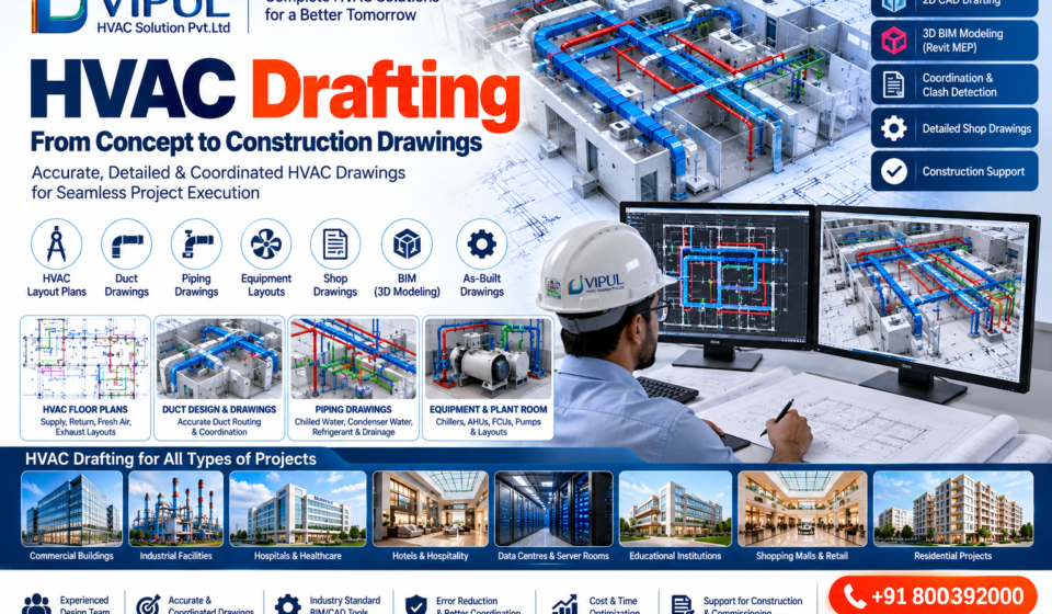

HVAC Drafting: Complete Guide to HVAC CAD Drawings, Shop Drawings & BIM
If you are planning a commercial building, industrial facility, hospital, hotel, pharmaceutical plant, data centre or large residential project, HVAC drafting is an essential part of converting HVAC engineering concepts into clear construction documentation.
HVAC drafting involves preparing detailed HVAC floor plans, duct layouts, piping drawings, equipment layouts, sections, schematics, shop drawings and BIM models that help engineers, contractors and installation teams understand exactly how the HVAC system should be installed.
ASHRAE’s HVAC Designer framework includes equipment selection and sizing, mechanical-room design, duct and piping design, and development of HVAC plans for permit and construction, demonstrating that drawings are closely connected to the engineering design process.
VIPUL HVAC SOLUTION PVT. LTD. provides HVAC engineering and project-execution support, including HVAC layouts and detailed drawings as part of its turnkey HVAC project workflow.
What Is HVAC Drafting?
HVAC drafting is the process of creating technical drawings that represent the layout, location, dimensions and installation details of an HVAC system.
An HVAC drawing can show:
- Air-conditioning equipment
- AHUs
- FCUs
- Chillers
- VRF/VRV outdoor units
- Indoor units
- Ductwork
- Diffusers
- Grilles
- Chilled-water piping
- Refrigerant piping
- Condensate drainage
- Fresh-air systems
- Exhaust systems
- Dampers
- Valves
- Control components
- Equipment rooms
- Shafts
- Service clearances
The purpose is to convert HVAC design information into documentation that can be coordinated and used during construction and installation.
HVAC Drafting vs HVAC Design
This distinction is important.
HVAC Design
HVAC design determines what the system needs to do and how it should perform.
It may include:
- Cooling-load calculations
- Heating-load calculations
- Airflow calculations
- Equipment selection
- Duct sizing
- Pipe sizing
- Static-pressure calculations
- Pump-head calculations
- Ventilation calculations
- System selection
- Energy analysis
HVAC Drafting
HVAC drafting converts approved engineering information into technical drawings and documentation.
It may include:
- Floor plans
- Duct layouts
- Piping layouts
- Equipment layouts
- Sections
- Details
- Schematics
- Shop drawings
- Coordination drawings
- As-built drawings
Therefore:
HVAC Design = Engineering
HVAC Drafting = Technical Documentation
In practice, the two activities are closely connected.
Why Is HVAC Drafting Important?
A good HVAC drawing provides a common reference for engineers, contractors, architects and installation teams.
Poorly coordinated duct or piping layouts can create problems involving space, access, noise, airflow, balancing and installation cost. ASHRAE specifically identifies space availability, noise, air leakage, balancing, fire/smoke control, initial cost and operating cost as important considerations in duct-system design.
Major benefits include:
- Better construction coordination
- Clear equipment positioning
- Accurate duct routing
- Easier installation
- Reduced site confusion
- Better coordination with other MEP services
- Easier quantity estimation
- Improved documentation
- Easier revision management
- Better as-built documentation
Types of HVAC Drafting Drawings
1. HVAC Floor Plan
An HVAC floor plan shows the HVAC arrangement on a building floor.
It can include:
- Supply ducts
- Return ducts
- Fresh-air ducts
- Exhaust ducts
- Diffusers
- Grilles
- FCUs
- Indoor VRF units
- Thermostats
- Duct dimensions
- Airflow information
A coordinated floor plan helps installation teams understand the intended HVAC layout.
2. HVAC Duct Layout
The duct layout is one of the most important HVAC drawings.
It can show:
- Supply-air ducts
- Return-air ducts
- Fresh-air ducts
- Exhaust ducts
- Duct dimensions
- Elbows
- Transitions
- Dampers
- VAV boxes
- Diffusers
- Grilles
- Flexible connections
ASHRAE maintains dedicated technical work on duct design and air distribution, including ductwork characteristics, construction and room-air distribution.
3. HVAC Piping Drawing
Piping drawings are used for systems such as:
- Chilled-water systems
- Condenser-water systems
- Refrigerant systems
- Condensate drainage
- Heating-water systems
A chilled-water piping drawing may identify:
- CHWS
- CHWR
- Pumps
- Valves
- Strainers
- Flow meters
- Balancing valves
- AHUs
- FCUs
- Chillers
ASHRAE’s pipe-design guidance covers pipe systems, materials, supports, stress considerations, expansion, flexibility and application requirements.
4. HVAC Equipment Layout
Equipment-layout drawings show the location and arrangement of HVAC equipment.
Typical equipment includes:
- Chillers
- Cooling towers
- Pumps
- AHUs
- FCUs
- PAC units
- VRF outdoor units
- Package AC units
- Fresh-air units
- Exhaust fans
The drawing should also consider access and maintenance requirements.
5. HVAC Plant Room Drawing
A plant-room drawing is used for centralized HVAC systems.
It may show:
- Chillers
- Pumps
- Headers
- Valves
- Expansion tanks
- Control panels
- Heat exchangers
- Cooling-tower connections
- Pipe routing
- Equipment clearances
Plant-room drafting is particularly important for large commercial and industrial projects.
6. HVAC Shop Drawings
HVAC shop drawings provide detailed information required for installation and construction.
They can include:
- Duct dimensions
- Duct routing
- Supports
- Equipment connections
- Pipe routing
- Equipment details
- Sections
- Installation details
- Access requirements
- Coordination information
HVAC drafting providers commonly distinguish floor plans, ductwork drawings, equipment layouts, piping drawings, sections and shop drawings as separate deliverables.
7. HVAC Section Drawings
Section drawings provide a vertical view of the HVAC installation.
They can help demonstrate:
- Ceiling heights
- Duct elevations
- Pipe elevations
- Equipment connections
- Shaft arrangements
- Ceiling coordination
- Structural-beam conflicts
- Service clearances
Sections become particularly useful when ceiling space is limited.
8. HVAC Schematic Drawings
Schematic drawings show the functional relationship between HVAC components.
Examples include:
- Chilled-water schematic
- Refrigerant schematic
- AHU schematic
- VRF piping schematic
- Control schematic
- Pump schematic
- BMS schematic
9. HVAC As-Built Drawings
As-built drawings document the HVAC installation as actually constructed.
They can be useful for:
- Future maintenance
- Renovation
- Equipment replacement
- Troubleshooting
- AMC
- Facility management
- Future expansion
HVAC CAD Drafting
HVAC CAD drafting generally uses computer-aided design software to create accurate 2D technical drawings.
CAD drawings can be prepared for:
- HVAC floor plans
- Duct layouts
- Piping layouts
- Equipment layouts
- Sections
- Details
- Schematics
- Shop drawings
The advantage of CAD is that project drawings can be revised, dimensioned, layered and documented systematically.
HVAC Revit BIM Drafting
Modern HVAC projects increasingly use BIM (Building Information Modeling) alongside conventional CAD.
A BIM workflow can represent HVAC systems in three dimensions and coordinate mechanical systems with architecture, structure and other MEP services.
ASHRAE’s HVAC Design pathway identifies BIM as a technology that can improve the flow of building information through planning, construction and operations.
Revit MEP can help with:
- 3D HVAC modelling
- Duct modelling
- Pipe modelling
- Equipment placement
- System connectivity
- Sections
- Schedules
- Coordination
- Clash detection
- Construction documentation
CAD vs BIM for HVAC Drafting
| Feature | HVAC CAD | HVAC BIM |
|---|---|---|
| 2D drawings | Yes | Yes |
| 3D modelling | Limited/possible | Core capability |
| Equipment information | Basic | Detailed model data |
| Duct modelling | Yes | Yes |
| Pipe modelling | Yes | Yes |
| Clash detection | Limited | Stronger workflow |
| Quantity schedules | Manual/assisted | Model-based |
| Coordination | Drawing-based | Model-based |
| Construction documentation | Yes | Yes |
| Facility information | Limited | More extensive |
The appropriate workflow depends on project size, client requirements and BIM execution requirements.
HVAC Clash Detection
One of the major advantages of coordinated HVAC BIM is the ability to identify potential conflicts before installation.
For example:
HVAC duct + beam
HVAC pipe + electrical tray
Duct + sprinkler pipe
AHU + structural element
Pipe + ceiling
Finding these issues during design coordination can reduce the need for expensive site modifications.
ASHRAE’s BIM guidance and certification material recognizes BIM standards and coordination as part of HVAC documentation and professional practice.
HVAC Drafting Workflow
A professional HVAC drafting process can follow these steps.
Step 1: Collect Architectural Drawings
Required inputs may include:
- Floor plans
- Sections
- Elevations
- Ceiling plans
- Room dimensions
- Building orientation
Step 2: Review HVAC Design Criteria
Review:
- Cooling load
- Indoor conditions
- Outdoor conditions
- Ventilation requirements
- Equipment selection
- Airflow
- System type
Step 3: Select HVAC Equipment
Depending on the project:
- VRF
- Chiller
- AHU
- FCU
- PAC
- Package AC
- Ducted AC
- Fresh-air unit
Step 4: Develop HVAC Layout
Prepare:
- Equipment locations
- Duct routing
- Pipe routing
- Diffuser locations
- Grille locations
- Shaft locations
Step 5: Coordinate With Other Services
Coordinate with:
- Architecture
- Structural
- Electrical
- Plumbing
- Fire fighting
- Interior/ceiling design
Step 6: Prepare Detailed Drawings
Develop:
- Plans
- Sections
- Details
- Schematics
- Equipment schedules
- Shop drawings
Step 7: Review and Revise
Check:
- Dimensions
- Airflow
- Equipment locations
- Service access
- Ceiling coordination
- Duct routing
- Pipe routing
Step 8: Issue Construction Documentation
After appropriate engineering review and approval, drawings can be issued for construction.
What Information Is Required for HVAC Drafting?
A drafting team normally needs project information such as:
Architectural Information
- DWG/PDF floor plans
- Building sections
- Ceiling plans
- Room usage
- Building elevations
HVAC Engineering Information
- Cooling-load calculations
- Equipment schedule
- Airflow
- Duct sizes
- Pipe sizes
- Equipment dimensions
- Design temperatures
- Fresh-air requirements
Project Requirements
- Applicable codes
- Client standards
- Drawing standards
- Layer standards
- Title-block requirements
- BIM requirements
- LOD requirements, where applicable
HVAC Drafting for Different Industries
Commercial Buildings
HVAC drafting can cover:
- Offices
- Shopping malls
- Showrooms
- Corporate buildings
- Retail facilities
Hospitals
Hospital HVAC documentation may need careful coordination of:
- Air distribution
- Fresh air
- Exhaust
- Pressure relationships
- Filtration
- Specialized rooms
Pharmaceutical Facilities
Drafting may include detailed layouts for:
- AHUs
- Duct systems
- Cleanrooms
- Process areas
- Fresh-air systems
- Exhaust systems
- Pressure-control systems
Data Centres
HVAC drawings may include:
- PAC/CRAC units
- CRAH units
- Supply-air pathways
- Return-air pathways
- Cooling-water systems
- Redundancy arrangements
- Equipment clearances
Industrial Buildings
Industrial HVAC drawings can cover:
- Process cooling
- Factory ventilation
- Exhaust
- AHUs
- Chillers
- PAC
- Fresh-air systems
HVAC Drafting for Chiller Systems
A chiller project can require multiple drawings.
Chiller Plant Drawings
- Chiller layout
- Pump layout
- Cooling tower layout
- Chilled-water schematic
- Condenser-water schematic
Piping Drawings
- CHWS
- CHWR
- CWS
- CWR
- Bypass lines
- Valves
- Headers
Equipment Drawings
- Chillers
- Pumps
- Cooling towers
- Heat exchangers
The final drawing package depends on project requirements.
HVAC Drafting for VRF/VRV Systems
VRF/VRV drafting may include:
- Indoor-unit layout
- Outdoor-unit layout
- Refrigerant piping
- Branch piping
- Controllers
- Condensate drainage
- Pipe sizes
- Equipment schedules
- Installation details
The manufacturer’s installation requirements and project design criteria should be followed when preparing final construction documentation.
HVAC Drafting for AHU Systems
AHU drafting can include:
- AHU location
- Supply duct
- Return duct
- Fresh-air duct
- Exhaust duct
- Chilled-water piping
- Condensate drain
- Dampers
- Filters
- Access panels
- Service clearances
HVAC Drafting Software
Common technologies used in HVAC drafting and BIM workflows include:
AutoCAD
Useful for:
- 2D HVAC layouts
- Duct drawings
- Piping drawings
- Sections
- Shop drawings
Revit MEP
Useful for:
- BIM
- 3D HVAC modelling
- Coordination
- Schedules
- Documentation
Navisworks
Useful for:
- Model coordination
- Clash detection
- Project review
Other tools may also be used depending on the project requirements.
How Much Does HVAC Drafting Cost?
There is no single fixed HVAC drafting price.
Pricing can depend on:
- Building area
- Number of floors
- HVAC system type
- Drawing quantity
- 2D vs BIM
- LOD requirements
- Project complexity
- Number of revisions
- Coordination requirements
- Shop-drawing requirements
- Timeline
For example, a small office HVAC layout will generally require a different level of effort from a multi-floor hospital, pharmaceutical plant or data centre.
A project-specific quotation is therefore more appropriate than a generic per-square-foot price.
Common HVAC Drafting Mistakes
Avoid these common problems:
1. Drafting Without Proper Design Inputs
Drawings should be based on approved engineering information.
2. Ignoring Ceiling Space
Large ducts and pipes require adequate space.
3. Poor MEP Coordination
HVAC should be coordinated with electrical, plumbing, fire protection and structure.
4. Missing Service Access
Equipment must remain accessible for maintenance.
5. Incorrect Duct Dimensions
Incorrect sizing can affect airflow and system performance.
6. Incorrect Equipment Clearances
Equipment layouts should consider manufacturer’s requirements and maintenance access.
7. Not Updating Revisions
Construction drawings should have controlled revision information.
Why HVAC Drafting Quality Matters
HVAC drafting is not simply about drawing lines on a CAD screen.
A technically useful drawing needs to communicate:
What equipment is required?
Where should it be installed?
How should the duct or pipe be routed?
What size should it be?
How does it connect to other components?
Can technicians access the equipment?
Does it coordinate with the rest of the building?
These questions make HVAC drafting an important part of the overall engineering and construction process.
HVAC Drafting Services by VIPUL HVAC SOLUTION PVT. LTD.
VIPUL HVAC SOLUTION PVT. LTD. provides HVAC engineering and project-execution support for commercial, industrial and institutional applications.
Its published turnkey HVAC workflow includes design, load calculation, equipment selection, installation, testing and commissioning, with HVAC drawings and layouts forming an important part of project documentation.
HVAC Drafting & Documentation Support Can Include:
- HVAC floor plans
- Duct layouts
- HVAC piping layouts
- Equipment layouts
- AHU layouts
- Chiller layouts
- VRF/VRV layouts
- Fresh-air layouts
- Exhaust layouts
- HVAC sections
- HVAC details
- Schematic diagrams
- Shop drawings
- Coordination drawings
- As-built documentation
HVAC Project Applications
VIPUL can support HVAC requirements for:
- Commercial buildings
- Industrial facilities
- Hospitals
- Hotels
- Offices
- Pharmaceutical projects
- Data centres
- Server rooms
- Educational institutions
- Retail buildings
- Manufacturing facilities
Why Choose VIPUL HVAC SOLUTION?
Engineering-Focused Approach
HVAC drawings should be connected to the actual engineering requirements of the project.
Multiple HVAC Technologies
Support can cover:
- Chiller
- VRF/VRV
- AHU
- FCU
- PAC
- Ducted AC
- Package AC
- Ventilation
- Fresh-air systems
Project Documentation
Detailed HVAC drawings can help bridge the gap between design intent and site installation.
Installation & Commissioning
VIPUL’s turnkey HVAC offering extends beyond drawings into project execution, testing and commissioning.
Frequently Asked Questions About HVAC Drafting
What is HVAC drafting?
HVAC drafting is the preparation of technical drawings that represent HVAC equipment, ductwork, piping, air terminals, ventilation systems and associated components for engineering coordination and construction.
What is the difference between HVAC CAD and HVAC BIM?
HVAC CAD primarily focuses on computer-aided technical drawings, while HVAC BIM creates an information-rich model that can support 3D coordination, documentation and project information management.
What drawings are included in HVAC drafting?
Common deliverables include floor plans, duct layouts, piping layouts, equipment layouts, sections, details, schematics, shop drawings, coordination drawings and as-built drawings.
Is HVAC drafting the same as HVAC design?
No. HVAC design involves engineering calculations, system selection and sizing, while drafting focuses on representing approved engineering information in technical drawings.
Which software is used for HVAC drafting?
AutoCAD is widely used for 2D drafting, while Revit MEP is commonly used for BIM-based HVAC modelling and documentation. Navisworks and other coordination platforms may be used depending on project requirements.
Why is HVAC shop drawing important?
HVAC shop drawings provide detailed construction information for ductwork, piping, equipment and installation. They help the project team coordinate and understand the intended installation before work is executed.
Does HVAC drafting include duct design?
HVAC drafting can represent duct design through layouts, dimensions, sections and details. The underlying engineering design and sizing should come from the responsible HVAC design process.
Can HVAC drafting be done in 3D?
Yes. BIM software such as Revit MEP can be used to develop 3D HVAC models and coordinated construction documentation.
Conclusion
HVAC drafting is an essential link between HVAC engineering and construction. From a simple commercial office to a large industrial plant, hospital, pharmaceutical facility or data centre, accurate HVAC drawings help communicate equipment locations, duct routing, piping, air distribution and installation requirements.
A professional HVAC drafting workflow can combine engineering information + CAD documentation + BIM coordination + shop drawings + construction support.
For HVAC design, drafting, installation, commissioning and maintenance support, contact:
VIPUL HVAC SOLUTION PVT. LTD.
Complete HVAC Solutions for a Better Tomorrow
HVAC Design | HVAC Drafting | Chiller | VRF/VRV | AHU | FCU | PAC | Ducting | Ventilation | Installation | AMC
📞 +91 8000392000
📧 info@vipulhvacsolution.in
🌐 VIPUL HVAC SOLUTION PVT. LTD.
Important Links:
- Customized HVAC Design Services in India
- HVAC Load Calculator
- HVAC Turnkey Services Gujarat
- Chiller System Supplier & Contractor in Gujarat
- VRF Design Consultancy India
- AHU Supplier in India
- Precision Air Conditioning
- Ducted & Package Air Conditioning
- Indoor Air Quality Solutions
- HVAC Maintenance & AMC



[…] HVAC Drafting […]
[…] HVAC Drafting […]