
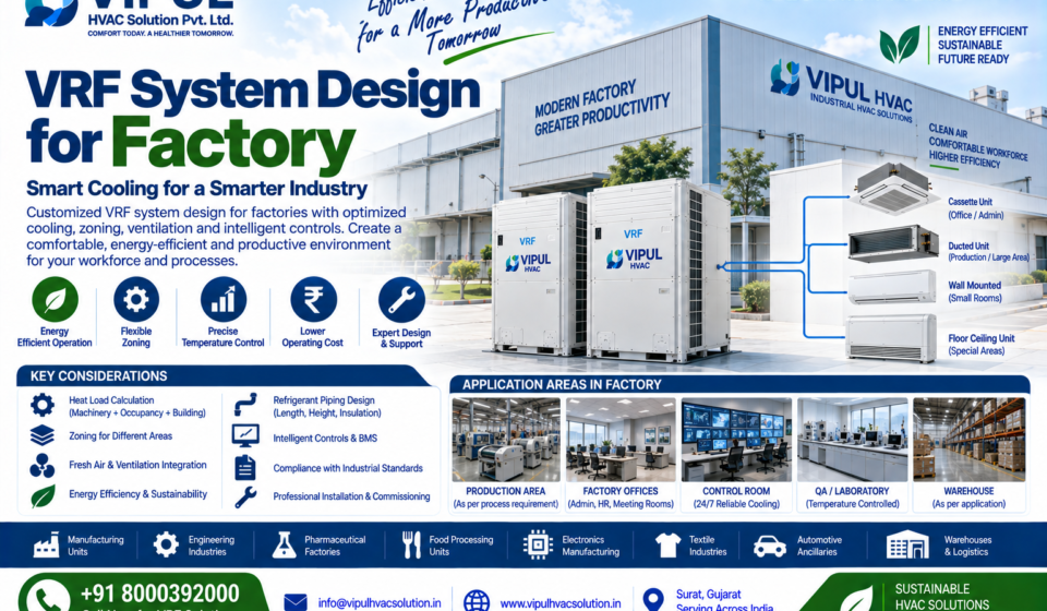

VRF System Design for Factory: Complete HVAC Design Guide
VRF system design for factory requires more than selecting VRF outdoor and indoor units. A factory HVAC system must consider production-area heat loads, machinery heat, occupancy, zoning, ventilation, fresh air, exhaust, humidity, operating schedules, refrigerant piping, controls, energy efficiency and maintenance access.
VRF is a variable-capacity DX technology that connects multiple indoor units to common outdoor units and allows zone-level control. ASHRAE describes VRF as a scalable system with variable capacity, distributed control and multiple indoor-unit configurations.
For factories, however, VRF should be selected according to the application. Production areas with substantial process heat, contaminants, dust, fumes or high ventilation requirements may require AHUs, package units, chillers, exhaust systems or dedicated ventilation in addition to—or instead of—VRF.
VIPUL HVAC Solution Pvt. Ltd. provides VRF/VRV system design, equipment selection, refrigerant piping design, zoning, commissioning and performance optimization for commercial and industrial HVAC applications.
What Is VRF System Design for a Factory?
VRF system design for a factory is the engineering process of determining how a variable refrigerant flow HVAC system should be configured to provide appropriate cooling or heating to different factory areas.
A factory VRF design can include:
- VRF outdoor units
- Indoor units
- Refrigerant piping
- Branch/refnet components
- Controllers
- Communication wiring
- Condensate drainage
- Electrical coordination
- Fresh-air systems
- Exhaust systems
- Ventilation
- BMS integration
- Testing and commissioning
A properly engineered design connects the actual factory heat load and operating requirements with the HVAC equipment rather than selecting equipment only by floor area.
Why Factory VRF Design Is Different From Office HVAC
An office primarily has comfort-related loads.
A factory may have significant additional heat from:
- Production machinery
- Motors
- Compressors
- Furnaces
- Welding equipment
- Electrical panels
- Conveyors
- Pumps
- Process equipment
- Lighting
- Production workers
- Material-handling equipment
- Outdoor-air requirements
For example, an office might have a relatively predictable cooling load, while a manufacturing area can experience substantial changes when production equipment starts or stops.
Therefore, factory HVAC design should be based on both building loads and process-related loads.
VIPUL’s industrial HVAC approach includes customized HVAC design and considers industrial applications alongside VRF, chillers, AHUs, ventilation and other systems.
How Does a VRF System Work in a Factory?
A simplified VRF arrangement is:
                 VRF OUTDOOR UNIT
                        │
              Refrigerant Piping
                        │
              ┌─────────┴─────────┐
              │                   │
          Branch Unit          Branch Unit
              │                   │
        ┌─────┼─────┐       ┌─────┼─────┐
        ↓     ↓     ↓       ↓     ↓     ↓
      Office  QA   Meeting  Lab  Admin  Control
       Area  Area   Room    Area  Area   Room
The VRF outdoor unit adjusts refrigerant flow according to the demand of connected zones.
ASHRAE identifies multiple indoor units connected to common outdoor units, variable capacity and distributed control as key characteristics of VRF systems.
Step-by-Step VRF System Design for Factory
1. Factory Site Survey
The first step is a detailed site survey.
The HVAC engineer should identify:
- Factory floor area
- Building height
- Production areas
- Office areas
- Utility rooms
- Electrical rooms
- Control rooms
- Laboratories
- QA/QC areas
- Meeting rooms
- Storage areas
- Existing HVAC equipment
- Roof space
- Outdoor-unit locations
- Electrical infrastructure
- Available service access
The survey should also identify production equipment that contributes heat.
2. Understand the Manufacturing Process
This is one of the most important parts of industrial HVAC design.
The engineer should understand:
What is manufactured?
How is it manufactured?
Which machines generate heat?
Which areas require fresh air?
Which processes produce fumes, dust, moisture or odors?
Which areas operate continuously?
For example:
Textile Factory
Potential HVAC considerations:
- Machinery heat
- Humidity
- Worker comfort
- Process requirements
- Fresh air
- Dust/fiber control
Pharmaceutical Factory
Potential requirements may include:
- Temperature control
- Humidity control
- Filtration
- Pressure relationships
- Cleanroom HVAC
- Fresh air
- Exhaust
Electronics Manufacturing
Potential requirements can include:
- Temperature stability
- Humidity control
- Clean air
- Specialized filtration
- Equipment heat removal
Food Processing
Potential requirements may include:
- Temperature
- Humidity
- Hygiene
- Ventilation
- Process exhaust
The HVAC architecture should therefore be selected according to the actual manufacturing process.
3. Divide the Factory Into HVAC Zones
Factory HVAC design should not treat the entire building as one zone.
Typical zones include:
| Factory Area | Typical HVAC Consideration |
|---|---|
| Production Area | Machinery + occupancy heat |
| Factory Office | Comfort cooling |
| Control Room | Equipment + continuous operation |
| Electrical Room | Electrical heat load |
| Server/IT Room | Dedicated cooling |
| QA Laboratory | Temperature + ventilation |
| Meeting Room | Occupancy + comfort |
| Reception | Comfort + occupancy |
| Warehouse | Application-dependent |
| Packaging Area | Process + comfort |
| Cleanroom | Specialized HVAC |
| Utility Room | Heat and ventilation |
| Canteen | Ventilation + cooling |
| Security Room | Comfort cooling |
Different zones can have different operating schedules and temperature requirements.
4. Calculate the Factory Cooling Load
The most important engineering calculation is the cooling-load calculation.
The load should include:
Building Heat Gain
- Walls
- Roof
- Windows
- Doors
- Solar radiation
Occupancy
Calculate heat generated by:
- Employees
- Operators
- Supervisors
- Visitors
Lighting
Factory lighting can contribute significant sensible heat.
Machinery
This is particularly important in manufacturing facilities.
Consider:
- Motor heat
- Machine heat
- Electrical losses
- Process equipment
- Compressors
- Pumps
- Production machinery
Ventilation
Outdoor air can add both sensible and latent cooling loads.
Infiltration
Consider uncontrolled outdoor-air entry through:
- Doors
- Loading bays
- Windows
- Building leakage
5. Consider Process Heat
A factory’s HVAC design can fail if process heat is ignored.
For example:
Machine Heat
     +
Lighting Heat
     +
People Heat
     +
Solar Heat
     +
Outdoor Air Load
     +
Infiltration
     =
Total Cooling Load
The actual calculation should be performed using engineering methods and project-specific data.
6. Select the VRF Capacity
Once the cooling load is established, the engineer can select:
- Indoor-unit capacity
- Outdoor-unit capacity
- Number of outdoor modules
- Combination ratio according to manufacturer requirements
- Cooling/heating capability
- Operating range
- Diversity
- Refrigerant piping arrangement
VIPUL’s VRF design service includes indoor and outdoor unit selection as part of its system-design scope.
7. Select the Right Indoor Units
Depending on the factory application, different indoor units may be appropriate.
Ducted Indoor Units
Useful where air needs to be distributed through ductwork.
Potential applications:
- Offices
- Control rooms
- QA areas
- Selected production areas
Cassette Units
Can be considered for suitable:
- Offices
- Meeting rooms
- Showrooms
- Administrative spaces
Wall-Mounted Units
Potentially suitable for smaller enclosed areas where appropriate.
Concealed Units
Useful when architectural appearance and concealed installation are important.
The final indoor-unit selection should be based on airflow, room layout, heat load, noise, maintenance access and application.
8. VRF Refrigerant Piping Design
Refrigerant piping is a critical part of VRF design.
The design should consider:
- Pipe diameter
- Total pipe length
- Equivalent length
- Vertical height
- Branch connections
- Refrigerant velocity
- Oil return
- Insulation
- Manufacturer limitations
- Refrigerant charge
- Service access
A typical system can be represented as:
Outdoor Unit
↓
Main Refrigerant Pipe
↓
Branch/Refnet
↓
Indoor Units
The actual pipe sizes and maximum allowable lengths must always follow the selected manufacturer’s engineering data.
9. Outdoor Unit Location
Factory outdoor units may be installed on:
- Rooftops
- Service platforms
- External equipment areas
- Dedicated HVAC yards
Important considerations include:
Airflow
Avoid hot-air recirculation.
Maintenance
Provide sufficient service clearance.
Structure
Verify the supporting structure.
Noise and Vibration
Consider nearby offices and occupied areas.
Refrigerant Piping
Minimize unnecessary pipe length while remaining within manufacturer limits.
Safety
Provide appropriate access for technicians.
10. Fresh-Air Ventilation for Factory
A major mistake is assuming that VRF alone provides all factory ventilation requirements.
VRF is primarily a space-conditioning technology.
Factories may require separate:
- Fresh-air systems
- Exhaust fans
- Process exhaust
- Dust extraction
- Fume extraction
- Make-up air
- Heat recovery
- Air filtration
VIPUL’s ventilation offering includes fresh-air handling units, supply/exhaust fans, filters, dampers, heat recovery, airflow testing and balancing, with HVAC integration.
ASHRAE also treats ventilation and air distribution as distinct engineering considerations within HVAC design.
VRF + Fresh Air System for Factory
A conceptual arrangement could be:
                 OUTDOOR AIR
                      ↓
                    FAHU
                      ↓
             FILTER + COOLING
                      ↓
              FRESH AIR DUCT
                      ↓
             FACTORY ZONE
                      ↑
                      │
                 VRF COOLING
                      │
               INDOOR UNITS


PROCESS AREA ─────→ EXHAUST SYSTEM
The exact system depends on the production process.
11. Factory Exhaust Design
Certain factories require specialized exhaust.
Examples include:
- Welding fumes
- Chemical vapors
- Heat
- Smoke
- Dust
- Odors
- Moisture
- Process gases
These should generally be addressed through appropriate source capture and exhaust engineering, rather than attempting to solve the problem using ordinary comfort-air-conditioning equipment.
12. VRF for Factory Offices
VRF can be particularly useful for factory office areas.
Possible applications include:
- Administration
- HR
- Accounts
- Conference rooms
- Engineering offices
- Management offices
- Reception
- Training rooms
Advantages can include:
- Individual zoning
- Flexible indoor-unit selection
- Centralized control
- Part-load operation
- Flexible piping
- BMS integration
VIPUL lists VRF/VRV as a core HVAC product and describes its systems as providing flexible zoning and precise control.
13. VRF for Factory Control Rooms
Control rooms may have a relatively high cooling requirement because of:
- PLC panels
- Computers
- Monitoring equipment
- Displays
- Electrical equipment
- Continuous occupancy
In some applications, dedicated or redundant cooling may be more appropriate than simply connecting the room to a general factory VRF system.
The design should consider the consequences of HVAC failure.
14. VRF for Electrical Rooms
Electrical rooms can have significant internal heat gains.
The HVAC design should consider:
- Transformer heat
- Electrical panels
- Drives
- UPS equipment
- Continuous operation
- Required environmental conditions
Depending on the equipment and room requirements, dedicated cooling may be required.
15. VRF for Cleanrooms
Cleanroom applications require much more than comfort cooling.
A cleanroom HVAC design can involve:
- AHUs
- HEPA filtration
- Temperature control
- Humidity control
- Pressure control
- Air changes
- Airflow patterns
- Fresh air
- Return air
- Monitoring
Therefore, VRF may support selected spaces, while dedicated cleanroom HVAC architecture may be required for controlled production environments.
VRF vs Chiller for Factory
The choice between VRF and a chilled-water system depends on the factory.
| Factor | VRF | Chiller System |
|---|---|---|
| Zone control | Excellent | Possible |
| Distributed cooling | Yes | Via chilled-water network |
| Multiple indoor units | Yes | AHU/FCU |
| Large central plant | Application-dependent | Strong option |
| Refrigerant piping | Yes | No |
| Chilled-water piping | No | Yes |
| Large production cooling | Application-specific | Often suitable |
| Process cooling | Usually not primary choice | Often considered |
| Office cooling | Strong option | Strong option |
| BMS integration | Available | Available |
| Fresh air | Separate system generally required | AHU/FAHU integration |
| Maintenance | VRF-specific | Chiller/plant-specific |
For a large manufacturing facility, a hybrid HVAC strategy may sometimes be more practical:
Chiller/AHU → Large Areas
FAHU → Fresh Air
Exhaust → Process Ventilation
Dedicated Cooling → Critical Equipment Rooms
The final selection should be based on engineering calculations and the factory process.
Energy Efficiency in Factory VRF Design
Energy efficiency should be considered during the design stage rather than after installation.
Important factors include:
1. Correct Capacity
Avoid unnecessary oversizing.
2. Zoning
Operate only the required areas.
3. Inverter Technology
Variable-capacity operation can help match output with demand.
4. Scheduling
Factory operating hours should be incorporated into the control strategy.
5. Temperature Setpoints
Use appropriate project-approved setpoints.
6. Ventilation Control
Fresh-air and exhaust systems should be coordinated with HVAC operation.
7. BMS
Central monitoring can help identify inefficient operating conditions.
8. Maintenance
Dirty filters and heat exchangers can reduce performance.
ASHRAE’s VRF guidance emphasizes that VRF should be considered as part of an integrated HVAC system rather than as an isolated product.
BMS Integration for Factory VRF
A modern factory may integrate VRF with a Building Management System (BMS).
Possible monitoring includes:
- Room temperature
- Setpoint
- Outdoor-unit status
- Indoor-unit status
- Fault alarms
- Operating schedule
- Energy data where supported
- Ventilation equipment
- Equipment alarms
This can help facility teams monitor HVAC operation from a central location.
VIPUL lists smart controllers and BMS integration among its VRF system features.
VRF Factory HVAC Design Workflow
A professional project can follow this sequence:
Step 1 — Requirement Study
Understand the factory and manufacturing process.
Step 2 — Site Survey
Collect architectural and engineering information.
Step 3 — Heat-Load Calculation
Calculate building, occupancy, machinery and ventilation loads.
Step 4 — HVAC Zoning
Separate areas according to usage and operating requirements.
Step 5 — System Selection
Compare VRF, chiller, AHU, package and other suitable systems.
Step 6 — VRF Selection
Select outdoor and indoor units.
Step 7 — Refrigerant Piping
Develop piping routes and sizes.
Step 8 — Ventilation
Design fresh-air and exhaust systems.
Step 9 — Controls
Develop local and centralized control strategy.
Step 10 — BMS
Integrate HVAC equipment where required.
Step 11 — BOQ
Prepare technical specifications and quantities.
Step 12 — Installation
Install equipment, piping, drainage, controls and electrical interfaces.
Step 13 — Testing
Test equipment and system operation.
Step 14 — Commissioning
Verify performance against project requirements.
Step 15 — AMC
Establish preventive maintenance and service schedules.
Common VRF Factory Design Mistakes
1. Selecting AC Based Only on Floor Area
Factory cooling loads can vary significantly because of machinery.
2. Ignoring Machinery Heat
Production equipment can contribute substantial heat.
3. Using VRF as a Substitute for Process Exhaust
Process fumes, dust and contaminants require appropriate ventilation/extraction.
4. Ignoring Fresh Air
Comfort cooling and ventilation are different functions.
5. Poor Refrigerant Pipe Design
Incorrect pipe sizing or excessive lengths can affect system operation.
6. Insufficient Maintenance Access
Equipment should remain accessible for inspection and service.
7. No Redundancy for Critical Rooms
Control rooms and critical equipment spaces may require a dedicated reliability strategy.
8. Ignoring Production Schedules
HVAC requirements can change between shifts.
9. No Commissioning
Equipment installation should be followed by appropriate testing and commissioning.
Benefits of Proper VRF System Design for Factory
A correctly engineered VRF installation can provide:
Flexible Zoning
Different rooms can have independent temperature control.
Energy-Efficient Operation
Variable-capacity operation can respond to changing demand.
Scalable Configuration
Multiple indoor units can be connected to suitable outdoor systems.
Better Comfort
Factory offices and occupied zones can be independently controlled.
Centralized Monitoring
Controls and BMS can provide operational visibility.
Flexible Installation
Refrigerant piping can provide flexibility where appropriate.
Reduced Unnecessary Cooling
Unused zones can be controlled according to operating requirements.
Why Choose VIPUL HVAC for Factory VRF System Design?
VIPUL HVAC Solution Pvt. Ltd. positions itself as an HVAC project partner for commercial, industrial and institutional applications. Its current portfolio includes VRF/VRV systems, chillers, AHUs, ducted/package AC, ventilation and other HVAC solutions.
For VRF projects, VIPUL’s listed capabilities include:
- Complete VRF system design
- Indoor-unit selection
- Outdoor-unit selection
- Refrigerant piping design
- Control logic
- Zoning
- Commissioning
- Performance optimization
- AMC support
For factories, this can be coordinated with:
VRF + Ventilation + Exhaust + AHU/FAHU + BMS + Ductwork
depending on the application.
VIPUL also lists HVAC solutions for factories and other industrial facilities.
VRF System Design for Factory in Gujarat
Industrial facilities in Gujarat can have very different HVAC requirements depending on the manufacturing process and building configuration.
Factory HVAC projects may be required for:
- Textile factories
- Pharmaceutical manufacturing
- Chemical industries
- Engineering industries
- Food processing
- Plastic manufacturing
- Automotive facilities
- Electronics manufacturing
- Packaging industries
- Warehouses
- Industrial offices
- Control rooms
- Laboratories
VIPUL HVAC provides HVAC services across Surat, Gujarat and nearby regions and lists factories among the industries it serves.
Frequently Asked Questions
Is VRF suitable for factories?
VRF can be suitable for selected factory applications, particularly offices, control rooms, administrative areas and other zones requiring flexible comfort cooling. Large production areas with high process heat or specialized ventilation may require other HVAC systems or a hybrid approach.
Can VRF cool a factory production area?
Yes, it can be considered where the heat load, environment and ventilation requirements are compatible with VRF. However, machinery heat, process exhaust, dust, fumes and outdoor-air requirements must be evaluated first.
Is VRF suitable for industrial offices?
Yes. Industrial offices are often suitable for VRF because they benefit from independent zone control and flexible indoor-unit configurations.
Does VRF provide fresh air to a factory?
VRF itself should not automatically be considered the factory’s complete fresh-air system. A dedicated FAHU/AHU or other ventilation system may be required depending on the application.
Can VRF and AHU work together?
Yes. VRF can be integrated with suitable air-handling arrangements, subject to the selected equipment and design. VIPUL provides VRF as well as AHU and ventilation solutions.
Is VRF better than a chiller for a factory?
There is no universal answer. The decision depends on factory size, cooling load, process heat, zoning, ventilation, operating schedule, redundancy, capital cost and lifecycle cost.
How is factory VRF capacity calculated?
Capacity should be determined through an engineering cooling-load calculation that considers building heat gain, occupancy, lighting, machinery, ventilation, infiltration and other relevant loads.
Can factory VRF be connected to BMS?
Yes, compatible VRF systems can support centralized control and BMS integration. The exact integration depends on the manufacturer and selected control architecture.
Conclusion
VRF system design for factory requires application-specific HVAC engineering. The correct design starts with understanding the manufacturing process and calculating the actual cooling load before selecting VRF equipment.
A complete factory HVAC strategy may combine:
Cooling Load Calculation
VRF can be an effective solution for appropriate factory zones, particularly offices, control rooms and other spaces requiring flexible temperature control. For high-load production areas, cleanrooms or process environments, the HVAC system should be selected according to the actual process and environmental requirements.
For VRF system design for factory in Gujarat, contact VIPUL HVAC Solution Pvt. Ltd.
📞 +91 8000392000
📧 info@vipulhvacsolution.in
🌐 vipulhvacsolution.in
Important Links:
- VRF system for factory
- VRF design for factory
- Factory HVAC system design
- Industrial VRF system
- VRF HVAC design
- Factory air conditioning system
- Industrial HVAC contractor
- VRF installation for factory
- Factory HVAC consultant
- VRF system design Gujarat
- Industrial HVAC solutions Gujarat
- VRF contractor Gujarat
- Factory cooling system
- HVAC design for manufacturing plant